The Effects of Coil Selection with Outside Air Loads
HVAC and process heating/cooling must deal with the added tonnage created by using fresh air from outside. Most times, the requirement for fresh air is mandatory and can go from 10% all the way to 100 % of the system air flow. There are numerous rules and regulations written to eliminate air flow quality problems, including bacteria and other micro-organisms, that can cause health problems. Rarely is a system designed with more fresh air introduction than is required by law.
We have all heard the term “economizer”. However, many in our industry do not really understand this term. An economizer is used when the temperature of the outside air is at or near the temperature of the return air in the system. An example would be a design return air temperature to an HVAC unit that is 80 degrees F. When the outside air temperature is below or reaches the design temperature, some or all the return air can be exhausted (sometimes stated as “relief “), and an outside air damper opens to bring in fresh air. One must equal the other. Whatever you exhaust must be made up with the introduction of new fresh air into the system. If I exhaust 4000 CFM, then 4000 CFM must be introduced through the outside air damper.
Let’s look at the design requirements of coils when all return air is used to size coils and when all fresh air is a requirement. This means that all the return air is exhausted and made up by new fresh air from outdoors. The tonnage load and other system requirements will increase dramatically. You can forget the term “400 CFM per ton”, because that’s based on an all-return air system. It’s not applicable in a fresh air system.
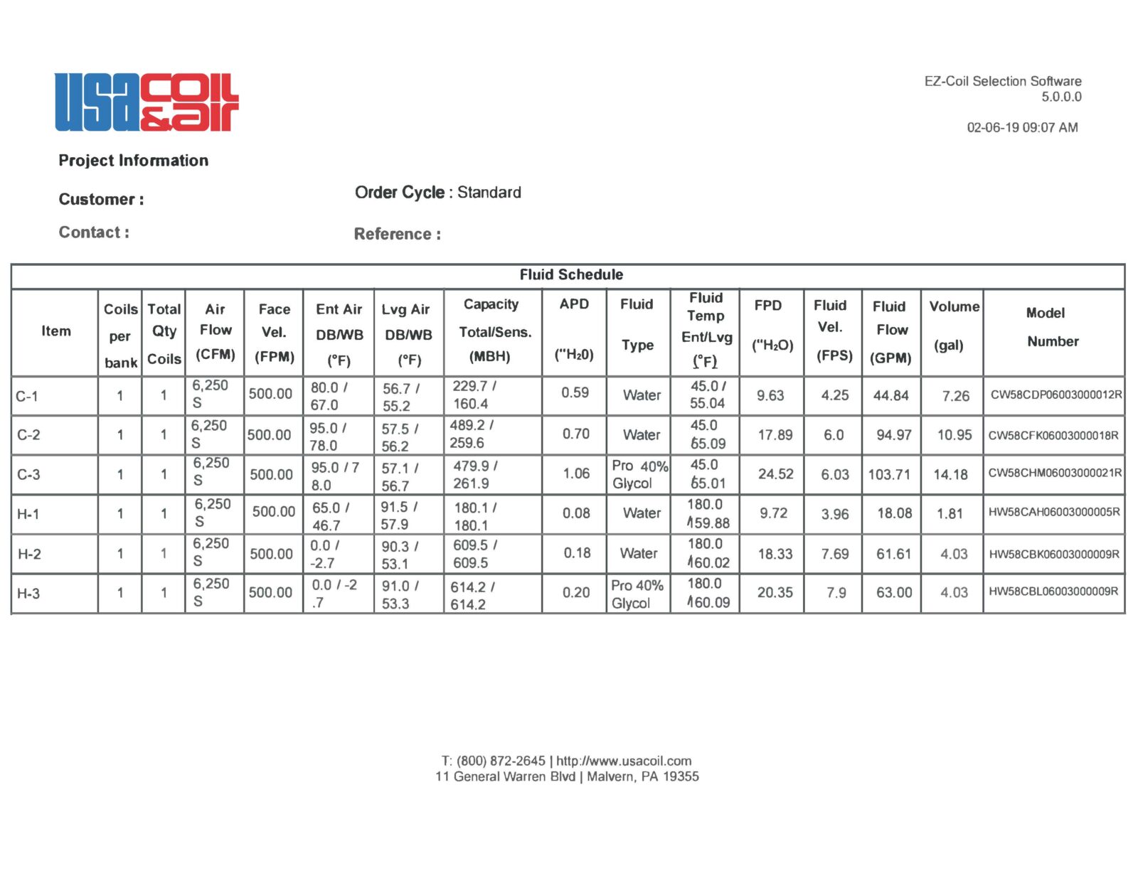
Attached are three water cooling selections (tagged C-1 to C-3) and three water heating selections (tagged H-1 to H). We will dissect these coil selections to show the major differences between all return air and all outside air systems. The selections are all the same construction, all finned-tube pattern, all the same size, and all the same CFM air flow. They are all either 10 degrees fluid temperature difference for cooling (TD) or 20 degrees fluid temperature for heating (TD).
Let’s look at the differences in the water-cooling selections:
C-1 is all return air (entering air temperature of 80/67). To take air down to 57 dry bulb or below requires a 4 row – 14 fins per inch selection and requires 44.84 GPM of water with a 9.63 feet of water pressure drop, and a .59-inch air pressure drop.
C-2 is the exact same performance run, except we changed the all return air temperature from (80/67) to an all outside air temperature of (95/78). To have the same leaving air temperatures, note the BTUH has increased 213% (from 229.7 MBH to 489.2 MBH). The GPM has increased to 213% as well (44.84 to 94.97). The water pressure drop is now up to 17.89 ft and the air pressure drop is up to .70 inches. Note that the coil is now 6 rows – 10 fins per inch.
C-3 is the same as C-2 with all fresh air. The difference is that we have added 40% propylene glycol. To achieve the same as C-2, the GPM has been increased to 103.71, fluid pressure resistance is up to 24.52 feet of water and air pressure drop is increased to 1.06 inches. Note that the coil is now 8 rows – 12 fins per inch.
Let’s look at the differences in the hot water heating selections:
H-1 is heating air from 65 degrees F up to just over 90 degrees F. You will need a 1 row – 8 fins per inch coil when you have 180 degree entering water and 18.08 GPM is required. Your water pressure resistance is 9.72 feet, and your air resistance is now .08 inches.
H-2 is the same performance run, except the entering air was changed to 0 degrees F in lieu of 65 degrees F, simulating an all fresh air system versus an all return air system. Now you have BTUH and GPM increases of 338% each, a water resistance increase of 90%, and an air resistance increase of 225%. Note that the coil is now 2 rows – 10 fins per inch coil.
H-3 is the same as H-2 except we have introduced 40% propylene glycol. Again, this increases the GPM, fluid and air side resistances. Note that the coil is now 2 rows – 11 fins per inch.
Fresh air isn’t free except in an economizer where the outside temperature has fallen to at or below the design return air temperature. We hope this analysis makes it easier to understand the major differences in coil selection with return and fresh air systems.