Test Product Page
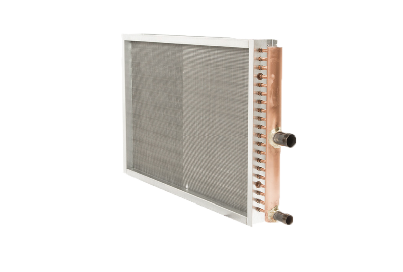
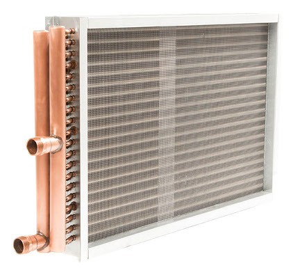
USA Coil & Air has an extensive library of OEM designs and can help with the replacement of all major OEM manufactured coils, including but not limited to: Carrier, Trane, McQuay, York, Heatcraft, Aerofin, American-Standard, Bohn, Colmac, Marlo and more.
Materials and Specifications
FINS
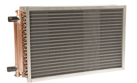
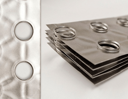
Secondary surface (fins) are of the plate-fin design using aluminum or copper, with die-formed collars. The fin design is to be flat, waffle, or sinewave in a staggered tube pattern to meet performance requirements. Collars will hold fin spacing at specified density and cover the entire tube surface. Aluminum properties are to be Alloy 1100 per ASTM B209, with O (soft) temper; copper is to be Alloy 11000 per ASTM B152-06 with soft (anneal) temper. Fins are to be free of oils and oxidations.
TUBES
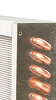
Tubes and return bends shall be constructed from seamless UNS C12200 copper conforming to ASTM B75 and ASTM B743. Properties shall be O50 light annealed, with a maximum grain size of 0.040mm. Seamless tubes are to be mechanically expanded into plate fins for maximum heat transfer.

HEADERS
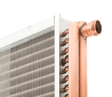
Headers are constructed of seamless UNS C12200, Type L copper material sized to match specified connection size. Headers are to have finished integral spin-closed ends designed to withstand test pressure. 1/4” vents and drains are provided for al fluid coils unless specified otherwise.
CONNECTIONS
Connection material can be copper, schedule 40 steel, or red brass pipe. The type of connection is to be sweat type, MPT or FPT, grooved, or flanged as required.
CASING
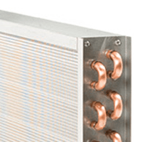
Coil casing material shall be 16-gauge, G90 galvanized steel. Heavier gauge and optional material casings are available as required to meet specification. Intermediate tube supports are to be provided on all coils 50” and longer in fin length. Coil casings on top and bottom of coils are to have double-flanged construction, allowing for vertical stacking of coils.
PRESSURE TESTING
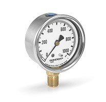
Coils comprised of round tubes shall be tested at 550 PSIG using dry nitrogen while submerged underwater. Dual-operator verification determines that all coils are leak-free. Sectional and cleanable coils designed with removable sections shall be leak tested at two times the recommended operating pressure, or 150 PSIG. Fluid coils shall be designed for 390+ PSIG water operating pressure (based on the tube and header O.D.) and guaranteed up to 200° F working temperature.
CERTIFICATION
All water coils designed with 1/2” or 5/8” tubes are to be AHRI performance certified and bear the AHRI symbol. Coils outside the scope of the AHRI’s standard rating conditions or the manufacturer’s certification program will be acceptable since the manufacturer is a current member of the AHRI coil certification program, and coils will be rated in accordance with AHRI Standard 410.
FLUID COILS (HW & CW)
Standard/Base in Bold Below
| Tube O.D. | Tube Thick | Optional Tube | Fin Thick. | Optional Fin |
| 3/8″ | .014 | .016 .022 | .006 | .0075 |
| 1/2″ | .016 | .025 | .006 | .0075 .010 |
| 5/8″ | .020 | .025 .035 .049 | .006 | .0075 .010 |
FLUID COILS (HW & CW)
Standard / Optional
| Fin Material | Aluminum | Optional -Copper; Stainless Steel |
| Casing Material | 16 gauge Galv. Steel | Optional - 12, 14, and 18 Gauge Galv. Steel • 12, 14, and 16 Gauge 304 & 316 Stainless Steel • 14 Gauge Aluminum |
| Tube Material | Copper | Optional - Stainless Steel, Cupro Nickel, Carbon Steel |
| Connection Material | Copper | Optional - Steel & Red Brass |
| Header Material | Copper | Optional - Stainless Steel, Cupro Nickel, Carbon Steel |
Technical Documents
Other Useful Stuff
Shipping
The equipment USA Coil & Air builds is specially made to order to meet your exact engineering requirements but we also understand time-critical projects require a quick turn around. Our expedited production program allows us to offer hot water coils to ship in as little as 10, 5, 3, and 1 working days guaranteed.
Shipping Option
Cost
20 Business Days
Standard Shipment
10 Business Days
Added Premium
5 Business Days
Added Premium
3, 2, & 1 Business Days
Call for pricing and availability
See our Shipping Schedule for all other HVAC equipment offered.

Questions? Need more information?
Please call us at 800-USA-COIL!
Or send us a message using the form to the left.
Latest From The Blog
View our latest blog news
-
What is Heat Transfer?
There are many terms used in the HVAC Industry. One that is often misunderstood is heat transfer. Wikipedia’s definition states that......
-
Invaluable Freeze Event Protection
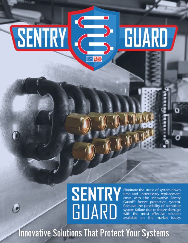
USA Coil & Air has been marketing our patented, freeze-damage water and steam coil line for over 25 years under the......
-
It’s Coil Replacement Season
The “holiday season” may be over, but the “coil replacement season” is in full swing in many areas of the country.......
