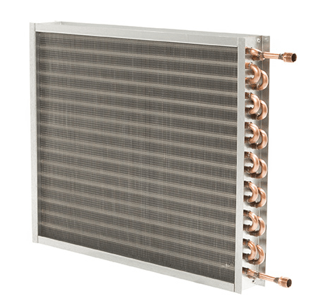
Duct Booster Coils- Selection and Sizing
Many projects require downstream duct mounted coils to heat or cool air to its final desired temperature. Normally there are upstream coils that regulate the leaving air temperature to a design intermediate level. The duct coil takes the air from that intermediate level to its final desired temperature. Many systems can vary the air flow or water volume to achieve a desired leaving air temperature for the load required at any given time. As an example, a 40-degree Fahrenheit day has a much lighter load than a 10-degree Fahrenheit day.
Selecting the coil mounting type
There are two basic heating coil designs, and you must choose one or the other.
- Flange type mounting where the incoming duct and outgoing duct match up with either a 1” or 1 ½” flange on both the inlet and outlet side of the coil
- Slip and drive type where the coil flat casing slips over the incoming and outgoing duct with screws and clips
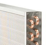
Selecting tube diameter for the coils
There are three different tube diameters as follows:
5/8” OD x .020” thick tube walls (options available at .025” and .035”) – Minimum GPM .8
1/2” OD x .017 thick tube walls (option available at .025) – Minimum GPM .6
3/8” OD x .014 thick tube walls (option available at .022) – Minimum GPM .4
Many small duct coils can have a very low volume of GPM at design conditions. On these smaller coils, you would select the tube diameter above to stay away from a systemic condition called “Laminar Flow”. This means the feet per second flow inside the tube is so low there can virtually be no heat transfer. It’s alright to have most coils at a larger tube diameter and smaller coils at a smaller tube diameter to keep the fluid flow higher and out of laminar flow problems.
Defining the face area of a coil
Remember that ducts are sized at 800 to 1200 FPM velocity. Heating coils at these velocities will have a very high air resistance due to two factors; 1) The higher the velocity, the higher the resistance and 2) The air is travelling so fast across the finned tube surface that you may need more rows in the direction of the air flow and/or more fins per inch.
Normally a velocity of 500 to 650 FPM is optimum, because the air is travelling at a velocity where you have good heat transfer and a reasonable air resistance. If you have a duct at 1000 FPM, and you need the coil velocity at 600 FPM, the coil face will be larger than the duct. A duct transition will be needed to go from the smaller duct up to the larger coil face and back down again on the leaving side to the original duct size.
EXAMPLE: Duct at 24 x 12 and 2000 CFM. The duct is 2 square feet (24 x 12 divided by 144). This means the duct velocity is 1000 feet per minute (2000 divided by 2 square feet). The coil will have to be 600 FPM (2000 CFM divided by 600 FPM equals 3.33 square feet required). You can add to the length of the coil and/or the height of the coil. In this case, a 33 x 15 coil (33” finned length x 15” finned height) is 3.44 square feet and equates to 581 FPM.
Selecting incoming water temperature and water temperature difference
Thirty years ago, most coils had 180 degrees Fahrenheit incoming water and a 20 degrees FTD. This means “in” at 180 degrees Fahrenheit and “out” at 160 degrees Fahrenheit (20 degrees F temperature difference). Many clients now desire much lower entering water temperatures. We have seen these as low as 105 degrees Fahrenheit. You may have a nice operating savings (105 degrees F versus 180 degrees F). However, it’s not free. The heat transfer is reduced tremendously at the much lower water temperature. A coil selection that would have been 1 row at 180 degrees Fahrenheit, may now be 2 or even 3 rows at the lower entering water temperature. You have dramatically increased your initial cost due to more expensive coils, and the air and water pressure drops will be much higher. It might be better at something in between 180 and 105 degrees Fahrenheit such as 140 degrees Fahrenheit. Have your coil selection specialist run a few examples, and you will be able to see the advantages and disadvantages of lower entering water temperatures.
Fins per inch maximum
Many systems have coils located in ducts that have never been cleaned on their air side surface in all their years of service. It’s important to understand that limiting the fins per inch may assist in keeping these coils from becoming plugged over an extended time-frame. We suggest a maximum of 10 fins per inch. If this restriction causes a coil to be selected at 2 rows versus 1 row in the direction of airflow, it may be better to have a larger coil face and keep the coil at 1 row but only 10 fins per inch.
USA Coil & Air can help you design the optimum coil(s) for your project that have a desirable initial cost but not at the expense of systematic or maintenance problems in the future. We ship boosters in 3 to 5 days on small projects or 4 weeks on larger projects.