Difficulties Replacing Old Central Station Air Handlers
Large indoor and outdoor central station air handlers eventually wear out and require either a complete refurbishment or replacement. They are usually located in ceilings, tight utility rooms, or mechanical rooms without access. Even the units that are on the roof or in a penthouse can require difficult, costly procedures to make replacement possible.


Older units will also have antiquated designs; i.e., single wall insulation, external drives, lack of access, and panels that often have problems being removed. These units also have corrosion in the wet area of the unit (cooling coil and drain pans) and damage to downstream sections. On the entering side, you can expect the older units to have leaky dampers and filter designs that are inefficient.
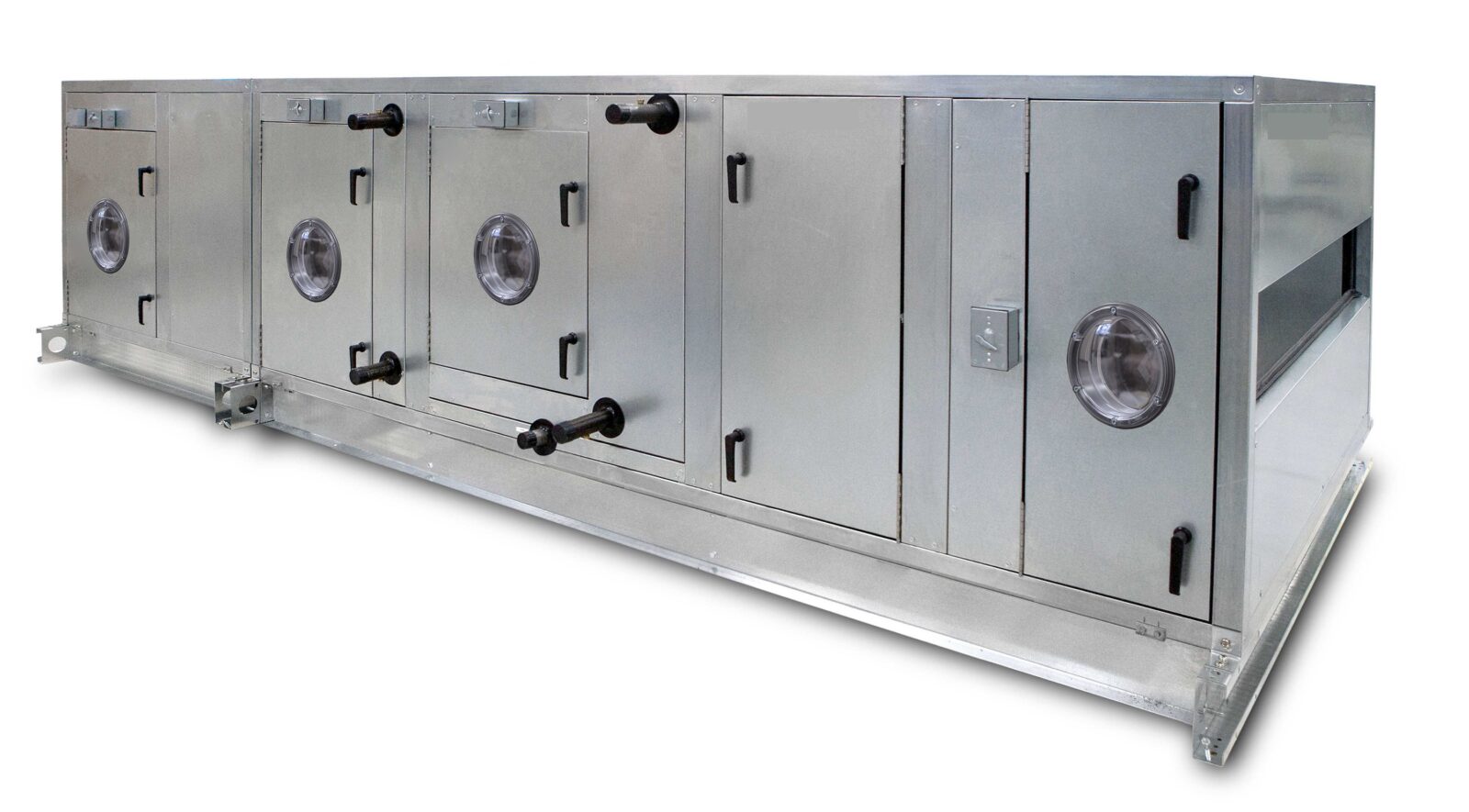
New units provide double wall construction, leak resistant dampers, expanded filter options, coil section corrosion resistance options, and a multitude of fan options that didn’t exist years ago. New units also have variable frequency drives and energy efficient motors, along with superior unit access, which makes it more desirable to replace a unit versus refurbishing an old one.
However, there is an industry-wide problem. Most owners and their servicing contractors don’t realize that many units can be replaced rather than refurbished. They see doorways, existing installed equipment, and downtime as huge issues and go the refurbishing route, missing the opportunity to get the enormous benefits of a new unit.
An old unit can be cut up and removed, but how do you get a new unit into place? We’ve simplified the process. You will need a new unit design that can pass through all the obstacles from the delivery point to the installation pad site. USA Coil & Air has a design that can be shipped in the maximum number of sections required to allow transporting to the pad site. Sometimes the sections will have to be broken down even further to accomplish this task. Our unit sections can be totally disassembled, transported to the installation area, and reassembled. We have worked with professional contractors across the country that have completely replaced large, sophisticated units over a weekend.
Once you have made the decision to replace the old unit(s), compiling information is very important to have the new unit(s) meet or exceed the capacity of the old unit(s) and fit without major modifications. Sometimes there are original submittals, or at least a job schedule from the original prints, that can provide us with the design criteria from years ago. These are often not available, so a thorough job site review by an air handler specialist is recommended. This review will include fan size, motor size, and coil face area. The depth and mixture of outside and return air can be used to establish the flow and capacity information needed.
A data sheet will need to be completed to replace air handler units, unless the original performance and dimensional data is known. Air handlers are a “box”, and we require the three overall dimensions of the box, which include a height (including external isolation) x width across the unit and the coil and access side locations. This data sheet also requests special issues that may be involved in mounting and installation; i.e., doorways, elevators, etc. Please remember that well-lit, clear photos will provide the air handler selector with much of the needed information.
Why refurbish when you can get all the benefits of a new unit with the up-to-date benefits of a new design. It’s easy if you select the right installer and USA Coil & Air as your manufacturer. Retrofit and replacement is our main business, and we were the 1st in the industry. Our motto is — Replacement Engineering Made Easy! Let our experts work for you.
Data Sheet Below:
AIR HANDLING UNIT WORK SHEET
PROJECT NAME __________________________________________________________
TAG __________ MANUF. ___________________ MODEL _______________________
(Circle One Option)
- SINGLE ZONE or MULTIZONE
- INDOOR or OUTDOOR*
*If outdoor unit, is a roof curb required? Y / N
- HORIZONTAL or VERT or FLOOR or CEILING
- DISCH ARRG’T: Top Horizontal or Bottom Horizontal
Vertical Top or Vertical Bottom
- COIL HAND: Right or Left
- ACCESS SIDE: Right or Left
- MIX BOX, DAMPER LOCATIONS:
Top & Back or Bottom & Back or Top & Bottom
Back & Side or Top & Side
- SECTIONS IN DIRECTION OF AIR FLOW – List from end of unit (where air enters) order of sections required
FILTER TYPES (List Specifics Below)
- COIL TYPE (IN DIRECTION OF AIR FLOW)
1st Coil __________________________ 2nd Coil ___________________________
3rd Coil __________________________ 4th Coil ___________________________
COIL INFORMATION
WATER COIL:
EAT DB / EAT WB ____________ / ____________
LAT DB / LAT WB ____________ / ____________
MBH_________ EWT __________ LWT ___________ GPM _________
Glycol Type _________________ % ___________
DX COIL:
EAT DB / EAT WB ____________ / ____________
LAT DB / LAT WB ____________ / ____________
MBH_________
Refrigerant Type ______________
Suction Temp _________________
Circuit Type: Single or Row Split or Intertwined
STEAM COIL:
EAT__________
LAT__________
MBH_________
Steam Pressure__________
FAN / MOTOR DATA
- CFM _____________ ESP __________ TSP ________________
- COIL FACE AREA SQ FT. _____________ OR FH” X FL”________________
- FAN TYPE _____________ MOTOR HP ______________ VOLTAGE _______
MOTOR TYPE ______________ SPECIAL _____________________________________
UNIT SIZE: LONG (IN DIRECTION OF AIR FLOW) _______________________
WIDTH (ACROSS COIL LENGTH) ___________________________
HEIGHT (INCLUDE RAILS AND ISOLATION) _______________
SPECIAL PROVISIONS FOR THIS UNIT: (List Below)
MOUNTING / INSTALLATION ISSUES
DOOR OR ACCESS OPENING SIZE _______________________________________
CORRIDOR SIZE ___________________________________________________________
ELEVATOR SIZE _____________________ DOOR OPENING ___________________
OTHER ISSUES: (List Below)
