Capacity Changes
It’s often difficult to understand circuitry on a chilled water coil. Changes to the “circuitry” and changes to the “tube diameter” will affect the overall capacity and pressure drops. Each time you change the circuitry on a coil selection, you have a positive, which relates to a higher capacity or lower fluid side pressure drop. The negative is either a lower capacity or a higher fluid side pressure drop. Simply put, you cannot have all positives when changing circuits on a coil selection.
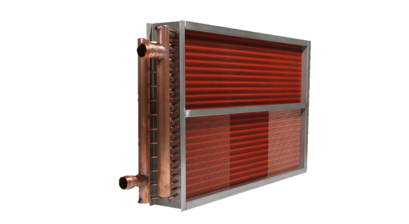
Example: Run a 4-row, 10 fin per inch chilled water coil, 30” finned height x 60” finned length (12.5 square feet of coil) that delivers 6,250 SCFM @ 80 dry bulb and 67 wet bulb to the fin side with 38 GPM of water entering at 45 degrees Fahrenheit to the tube side. The six selections below will only change the circuitry and the outside tube diameter.
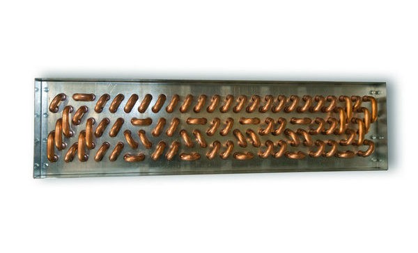
The 5/8” OD tube will be a 1.5” x 1.299” waffle fin and the ½” OD tube selections will be 1.25” x 1.082” waffle fin design. The center to center on tubes in each row will be 1.5” x 1.299” x the center to center back through the rows. Therefore, the 1.25” (the center to center on the tubes) x 1.082” (the center to center back through the rows). A 5/8” coil will have 20 tubes high in each row and the ½” coil will have 24 tubes in each row.
The following two charts show three types of industry standard circuits that all create “same end connections” for a 4-row coil.
| Tube Diameter | Circuit Type | Number of Feeds | Number of Passes |
| 5/8” | Half | 10 | 8 |
| 5/8” | Full | 20 | 4 |
| 5/8” | Double | 40 | 2 |
| ½” | Half | 12 | 8 |
| ½” | Full | 24 | 4 |
| ½” | Double | 48 | 2 |
|
Selection |
Description |
TBTUH |
SBTUH |
Leaving Air |
Water Velocity |
Water PD |
| 1 | 5/8” – Half | 198,929 | 158,820 | 56.9/56.9 | 4.16 FPS | 9.50’ |
| 2 | 5/8” – Full | 176,148 | 150,312 | 58.2/58.2 | 2.08 FPS | 2.85’ |
| 3 | 5/8” – Double | 148,208 | 140,125 | 59.7/59.7 | 1.04 FPS | 1.80’ |
| 4 | ½” – Half | 203,366 | 158,380 | 57.0/56.7 | 5.43 FPS | 17.51’ |
| 5 | ½” – Full | 183,825 | 153,055 | 57.8/57.8 | 2.72 FPS | 4.13’ |
| 6 | ½” – Double | 153,842 | 143,289 | 59.2/59.1 | 1.36 FPS | 2.02’ |
The lower number of tubes you feed, create the highest BTUH exchange. (See selections Number 1 and 4 in the second chart.) Conversely, they also have the highest water side pressure drops. Why? Because you have the highest water velocity shown in feet per second (FPS).
Also, note the major differences between the ½” OD selections and the 5/8” OD selections. With the same circuit type, you obtain a slightly higher total BTUH, but fall a little short on sensible BTUH with the ½” design. The other major difference is the much higher water pressure drop values with the ½” OD design. Why? Again, it is the higher water velocity that gives you more total BTUH, but higher water pressure drops as well.
There has been a proliferation of manufacturers offering only the ½” OD tube design and not offering 5/8” OD tubes anymore. The reason is simple. The ½” OD design is slightly less costly, and stocking one type of design is a lot easier than stocking both designs. There is a need for both designs, and the above comparisons prove that point. If you want a coil selection that meets the best and most efficient design, then both 5/8” and ½” designs need to be reviewed. Look at Selections 1 and 4 and imagine operating a system for 25 years with a water drop of 17.51’ versus 9.50’.
There are many other factors that relate to more efficient selections, they include fin design, tube thickness, and special circuitry. USA Coil & Air has ALL of them, and we make 99% of our selections in house. You are guaranteed the highest quality and the most efficient design that also fits your budget.